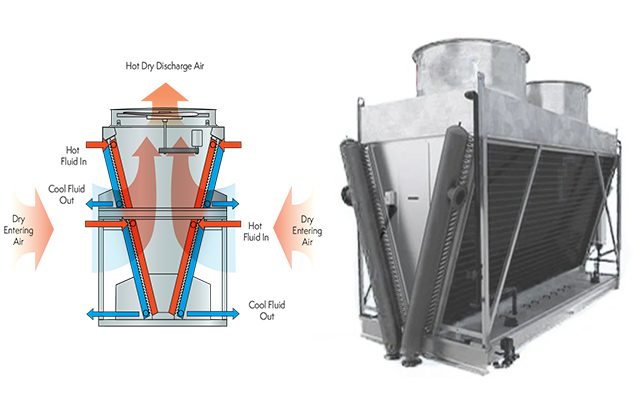
• The operating principle of a closed cooling tower: The closed cooling tower system (Figure 1) consists of two water circuits. One main circuit cools the chiller, circulating to the tower by the condenser pump of the water chiller system. The other circuit at the cooling tower circulates water through a pump located at the tower to reduce the temperature of the main water circuit through the heat exchange coil in the tower. The water in the tower will exchange heat directly with the air through a fan, lowering the water temperature and continuing to cool the main water circuit through the heat exchange coil.
• Advantages of the closed cooling tower: The main water circuit is completely closed, preventing contamination from outdoor air or water loss due to evaporation. Because of this advantage, closed cooling towers are often used in applications where the water in the main circuit needs to be isolated from the air or has already been treated, as compared to regular water.
• Applications of the closed cooling tower: Cooling systems for ships where seawater is used for cooling in the tower, treated water or glycol solutions used for cooling in industrial applications…
-
Open cooling tower

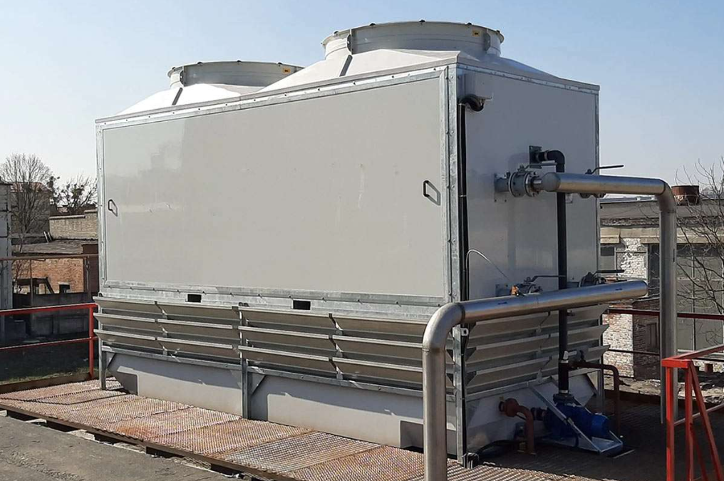
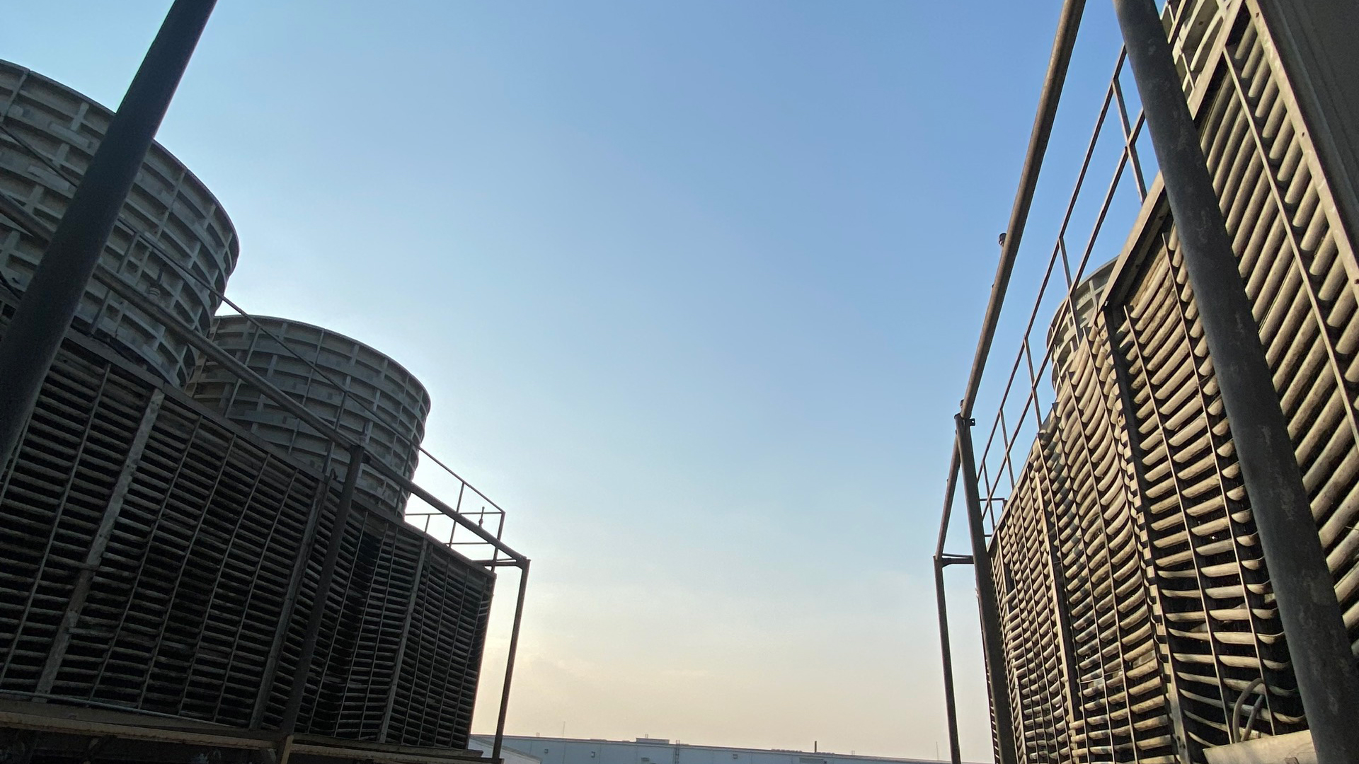
Image of an open cooling tower.
The Open Cooling Tower is the most commonly used type of cooling tower today. It is often used in air conditioning systems to cool the chiller systems of commercial and industrial buildings. Typical applications include skyscrapers, shopping malls, hospitals, convention centers, and factories…
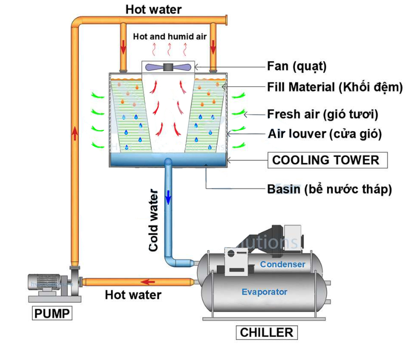
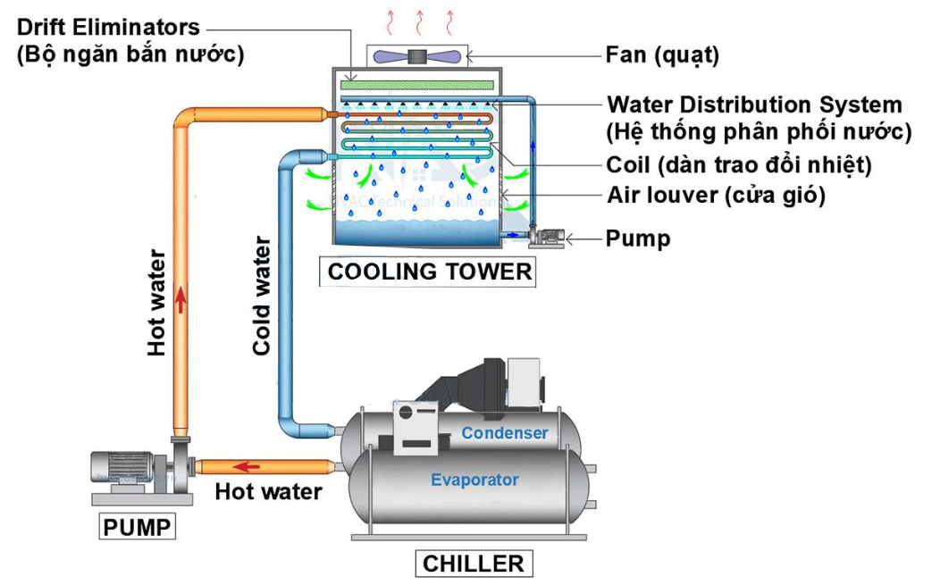
The schematic diagram of an open cooling tower.
The operating principle of an open cooling tower: The Open Cooling Tower (Figure 3a) uses water to exchange heat with the air. However, in an open cooling tower, there is only one main water circuit that is pumped from the chiller condenser to the tower. After cooling, the water returns to cool the chiller condenser. The water in the cooling tower exchanges heat with the air through the tower’s exhaust fan. A portion of the water evaporates into the air, thereby reducing the temperature and is then returned to the chiller condenser.
There are two main types of open cooling towers: counter flow and cross flow:
• Counter flow cooling tower: A cooling tower where the water and air flow in opposite directions.
• Cross flow cooling tower: A cooling tower where the water and air flow perpendicular or crosswise to each other.
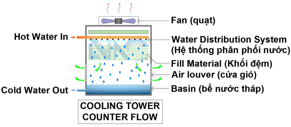
The structure of a counter flow cooling tower.
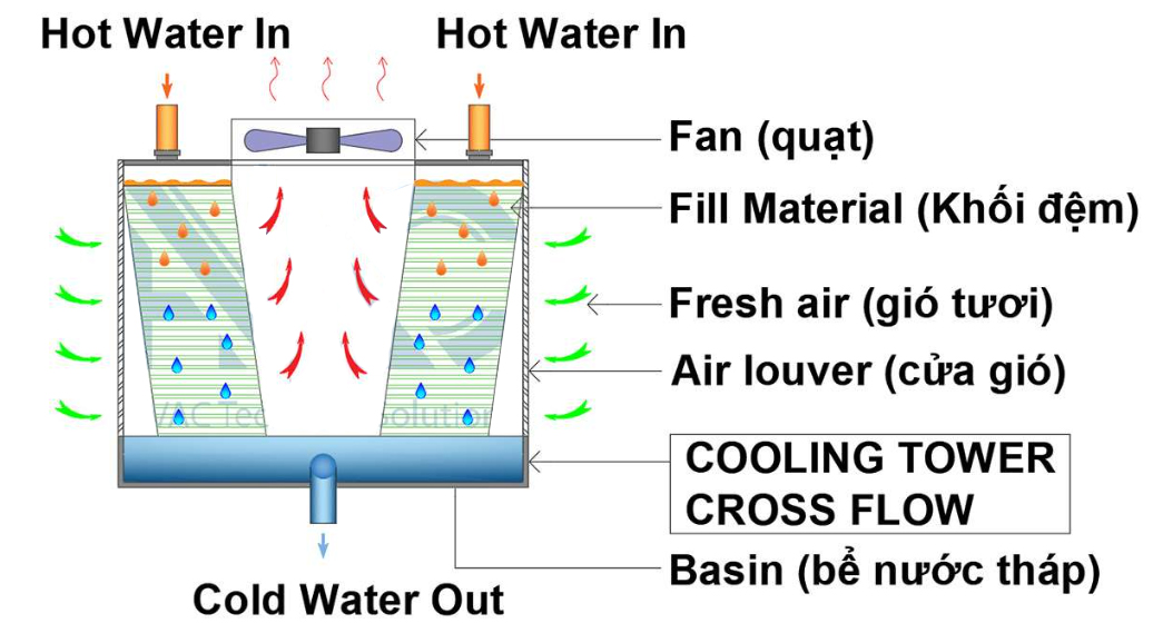
The structure of a cross flow cooling tower.
In addition, sometimes we also encounter a type of cooling tower with a forced draft fan, known as a Forced Draft Cooling Tower.
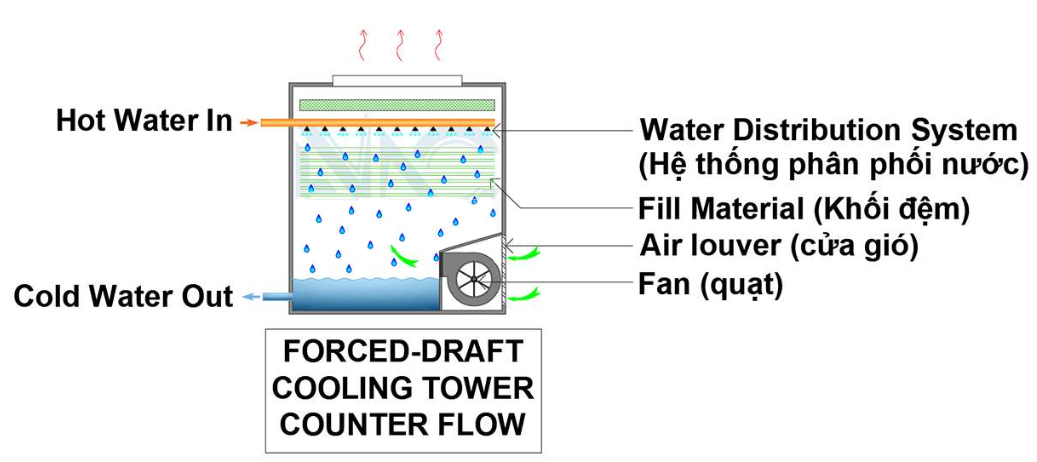
The structure of a forced draft cooling tower.
The operating principle of a Forced Draft Cooling Tower: Similar to open-type cooling towers, this type of tower uses a fan to push air from the bottom upwards. The air exchanges heat with the water from top to bottom. The water’s temperature is reduced, while the air absorbs heat and is expelled from the top of the tower. Forced Draft Cooling Towers are commonly used in industries that require high cooling performance.
III. Analysis of the schematic diagram of the cooling tower system in a water chiller.
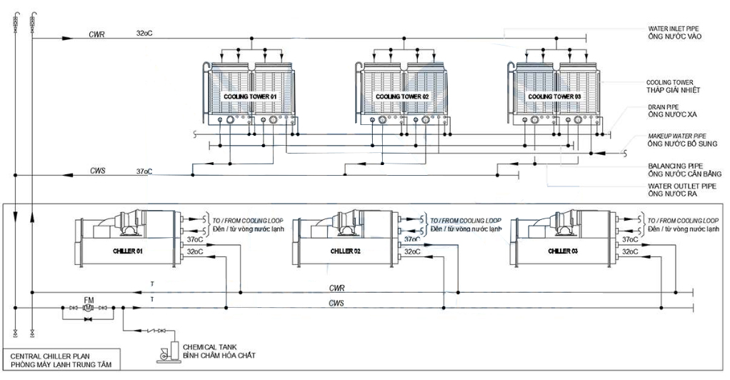
The schematic diagram of the water piping for the cooling tower in a water chiller system.
-
Operating principle
To make it easier to understand, let’s assume the typical inlet and outlet temperatures of the cooling tower are 37°C and 32°C, respectively, which means the temperature difference (AT in-out) of the tower is 5°C as shown in Figure 6.
The cooled water, after absorbing heat from the refrigerant in the condenser to release heat, exits the chiller at 37°C. This hot water is pumped up to the cooling towers through the water piping. In the cooling towers, the water is sprayed from top to bottom, exchanging heat with the air coming from outside, lowering the water temperature to 32°C. This cooled water will then continue to be pumped back to the condenser to release heat and maintain the chiller’s operation cycle.
-
Role and main functions of the water pipes and valves on the schematic
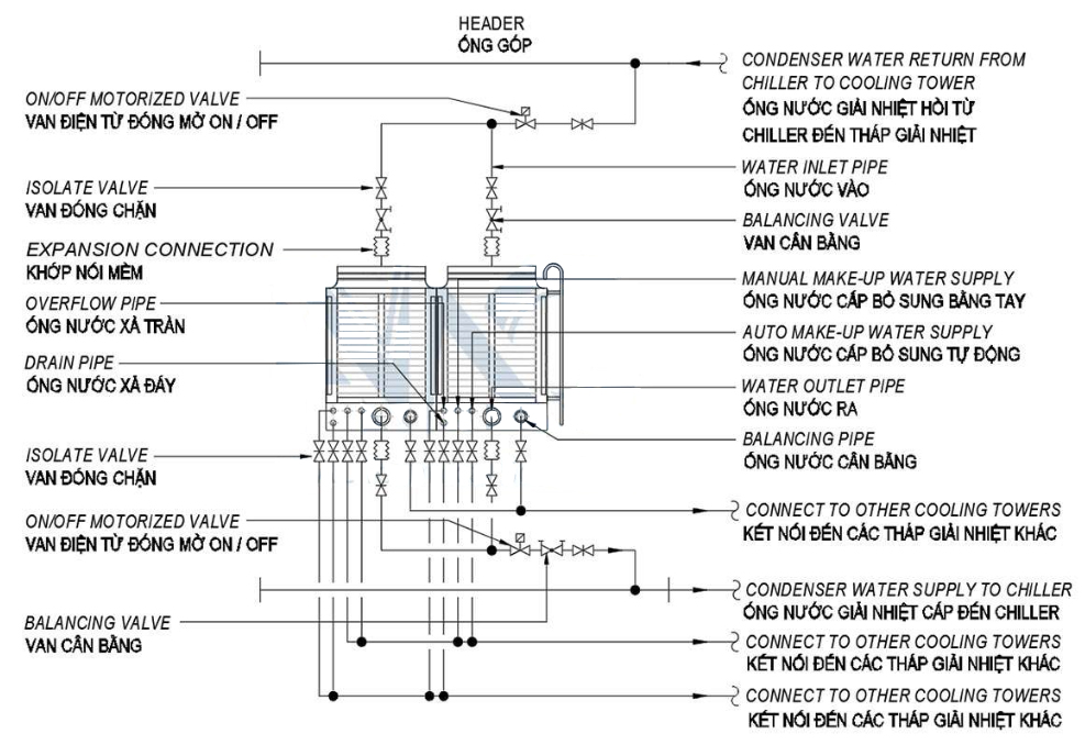
The detailed schematic diagram of the types of pipes and valves at the cooling tower.
From the above diagram, we can see that a typical cooling tower has 5 basic water circuits:
• The return water circuit from the chiller to the cooling tower.
• The supply water circuit to the chiller.
• The balancing water circuit between cooling towers.
• The supplemental water supply circuit, including the automatic water supply and manual quick supply.
• The discharge water circuit, including overflow discharge and bottom discharge of the tower.
In the cooling tower, there are mainly 2 types of valves:
• Shut-off valves, which are used to isolate the cooling tower for maintenance or inspection when needed.
• Solenoid valves on the water inlet and outlet pipes, used to open or close when the tower is operating or shut down.
Additionally, there are balancing valves; however, in systems that frequently operate in part-load mode, balancing valves are not very useful and can be removed when the towers are placed close together on the same plane.
IV. Selection of cooling towers
-
Quick selection of cooling towers under normal conditions
Use the cooling capacity of the chiller and refer to the cooling tower catalog to calculate the required cooling water flow. Typically, it is 13 liters per minute per ton of cooling capacity.
For example: If we have a 400-ton chiller, the cooling water flow will be 400×13 = 5200 liters/min. Use this flow value to refer to the corresponding cooling tower size, as some catalogs only show cooling water flow and do not specify the cooling capacity of the models.
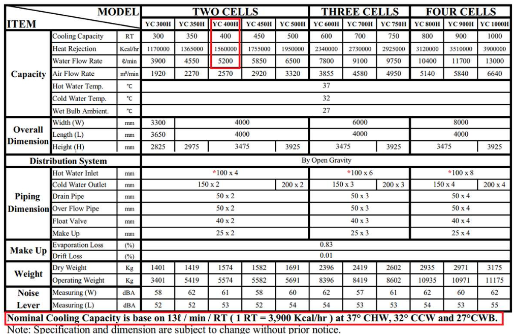
Select a cooling tower according to the catalog.
Note: In this selection method, most of the catalogs from suppliers are based on the condition that the ∆T in-out of the cooling tower is 5°C and the ∆T approach at the tower is 5°C.
Some common cooling tower suppliers available in Vietnam include: Liangchi, OCEAN, BAC, Sanjiu, Kumisai, Evapco, BKK, and Rinki.
2. Cooling Tower Selection through Calculation Analysis
To select the optimal cooling tower, we need to consider the following criteria and conditions:
• Determine the system’s operating configuration: Keep in mind that the number of cooling towers does not necessarily equal the number of chillers in the system. The number of cooling towers should be selected based on the part-load operation conditions of the building to balance cost and energy savings.
• Determine the appropriate type of cooling tower: As discussed earlier, each type of cooling tower has its own advantages and disadvantages. Choosing the right type will result in better operational efficiency for the system.
• Determine the fan type of the cooling tower: Many engineers focus on the cooling pumps and overlook the fans (variable speed, single-speed, or multi-speed). However, the cooling tower fan significantly impacts the system’s energy efficiency.
• Determine the condenser water inlet and outlet temperatures: This is also the inlet and outlet temperature for the cooling tower. It’s important to analyze the inlet and outlet water temperatures based on the system’s cooling capacity and operating conditions.
• Determine the wet bulb temperature of the environment and the temperature difference (approach) at the cooling tower: These parameters help select the appropriate tower size for different environmental conditions.
• Choose a cooling tower based on its performance specifications: Ensure that the cooling tower’s efficiency (I/s.kW) meets the energy efficiency standards.
• Calculate parameters for water flow, pipe sizes, and valve systems: Consider factors such as operation time, usage purpose, and system control strategy to select the most appropriate equipment.
3. Common Mistakes and Misunderstandings in Cooling Tower Design for Water Chiller Systems
a) Selecting a cooling tower based solely on cooling capacity and ignoring climate conditions
This is the most common mistake in design. When only the chiller’s cooling capacity is considered, the cooling tower size will always be the same if the chillers have the same capacity, regardless of the project location.
For example, for the same inlet and outlet temperatures of 37°C – 32°C in projects located in Ho Chi Minh City and Hanoi, the cooling tower selected in Hanoi must have a larger cooling capacity due to the difference in climate conditions.
b) Selecting a cooling tower without considering the approach temperature difference
The approach temperature is the temperature difference between the wet bulb temperature of the environment and the outlet water temperature from the cooling tower. This value significantly affects the size of the cooling tower and the cooling efficiency of the chiller. Many engineers rely on experience and select an approach temperature of 5°C, but in reality, this value can be analyzed and chosen within a range of 2°C to 5°C.
c) Selecting the same Delta T for the cooling tower as the Delta T for the chiller’s cooling circuit
Some less experienced engineers mistakenly believe that the ∆T for the condenser is the same as the ∆T for the evaporator. This is not correct. They are not necessarily the same and can differ in terms of the maximum ∆T.
d) Water overflow and water wastage in cooling towers due to lack of solenoid valves
In large-scale projects like factories, where cooling tower units usually run at full load, this issue may not occur. However, in commercial buildings like office towers, shopping centers, and hotels, where cooling load operates at varying percentages (part-load) frequently, this problem can easily occur if operators are not careful, leading to significant water wastage.
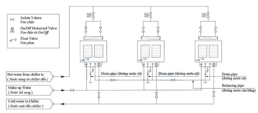
Figure a. Solenoid valve on the water inlet pipe of the cooling tower.
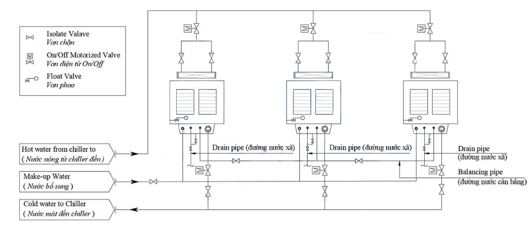
Figure b. Solenoid valve on the water inlet and outlet pipes of the cooling tower.
As seen in Figure a and Figure b, the differences are:
- Figure a shows only the solenoid valve on the water inlet pipe of the cooling tower.
- Figure b has solenoid valves for both the inlet and outlet pipes.
The design in Figure a is the main cause of water overflow in the cooling tower. We will analyze Figure a in the following operating case: When operating at full load, all cooling tower units are running, and the water flow through the towers is the same, so there is no water overflow. However, in the part-load operation (running at a percentage and not full load), for example, when only one chiller is operating, only one cooling tower will operate, while the other two cooling towers will be inactive. The solenoid valve for the operating tower is open, while the two non-operating towers will have their solenoid valves closed, preventing water from entering. On the other hand, the water outlet pipes of the three towers are simultaneously sucked back into the chiller condenser by the cooling pump. Since there is no solenoid valve to block the water flow, this suction causes the two non-operating towers to quickly lose water below the float valve level in their tanks. Supplementary water will be added to compensate for this loss, but in reality, the system is not lacking water, so it can be called a false water loss phenomenon in the system. The large suction force from the pump to the chiller is greater than the balancing water flow at the cooling tower basins, leading to water overflow in the operating tower. This overflow will drain through the overflow pipe, but in more serious cases, the water may overflow outside the tower, wasting water. Overflowing outside the tower is easy to notice, but overflowing through the tower’s overflow pipe can be difficult to detect and lead to significant water waste if not identified over a long period. Therefore, to ensure tight control of the system and prevent water overflow during low-load operation, it is essential to not only provide a balanced water line between the cooling towers but also to design solenoid valves on both the supply and return lines of the cooling tower, as shown in Figure b.
e) Choosing a too-small balancing pipe for the cooling towers: Water entering and leaving the cooling towers, though using a common manifold, is connected to each individual tower via separate pipes and controlled by valves. The amount of water lost or retained by the cooling towers depends on the installation location and operational factors, such as towers positioned in areas with more sunlight or wind, which will lose more water than others. Additionally, cooling towers located closer to the pump or with less resistance in their pipes will receive more water than other towers, as balancing water flow evenly in part-load conditions is challenging. Because the water distribution is uneven across the towers, when operating simultaneously, some towers will lose or draw more water than others. When the balancing pipe is too small or absent, towers losing more water may experience false water shortages and overflow, as previously described. In the case of closed cooling tower systems, where water inflow is low and water loss is high, and the rate of supplementary water is slow, the cooling pump may run dry, leading to damage. Therefore, the balancing water pipe between cooling towers plays a crucial role in ensuring the system runs smoothly without water wastage or ineffective cooling.
V. Selecting the Balancing Pipe Size Between Cooling Tower Units
For the balancing pipe size, we can refer to the guidelines provided by the cooling tower manufacturer or calculate it based on the water flow through the largest cooling tower unit in the system. In this case, the flow rate for the balancing pipe should be approximately 15% of the flow rate of the largest cooling tower in the system. Additionally, the table attached can be used to select the appropriate size for the balancing pipe between the cooling towers.
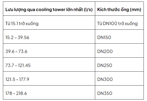

 Table of contents